Simple data flop flop example
module dff (data, clock, q);
input data;
input clock;
output q:
reg q;
always @(clock)
q <= data;
end
endmodule
Combinational logic using continuous assignment example
Think of what decoding you want like an address decoding for all bits to 0 and then create logic 1
assign address_dec = (address[3:0] == 4’b0000) 1 ? 0 ; //output 1 when all address bits are 0 else output 0
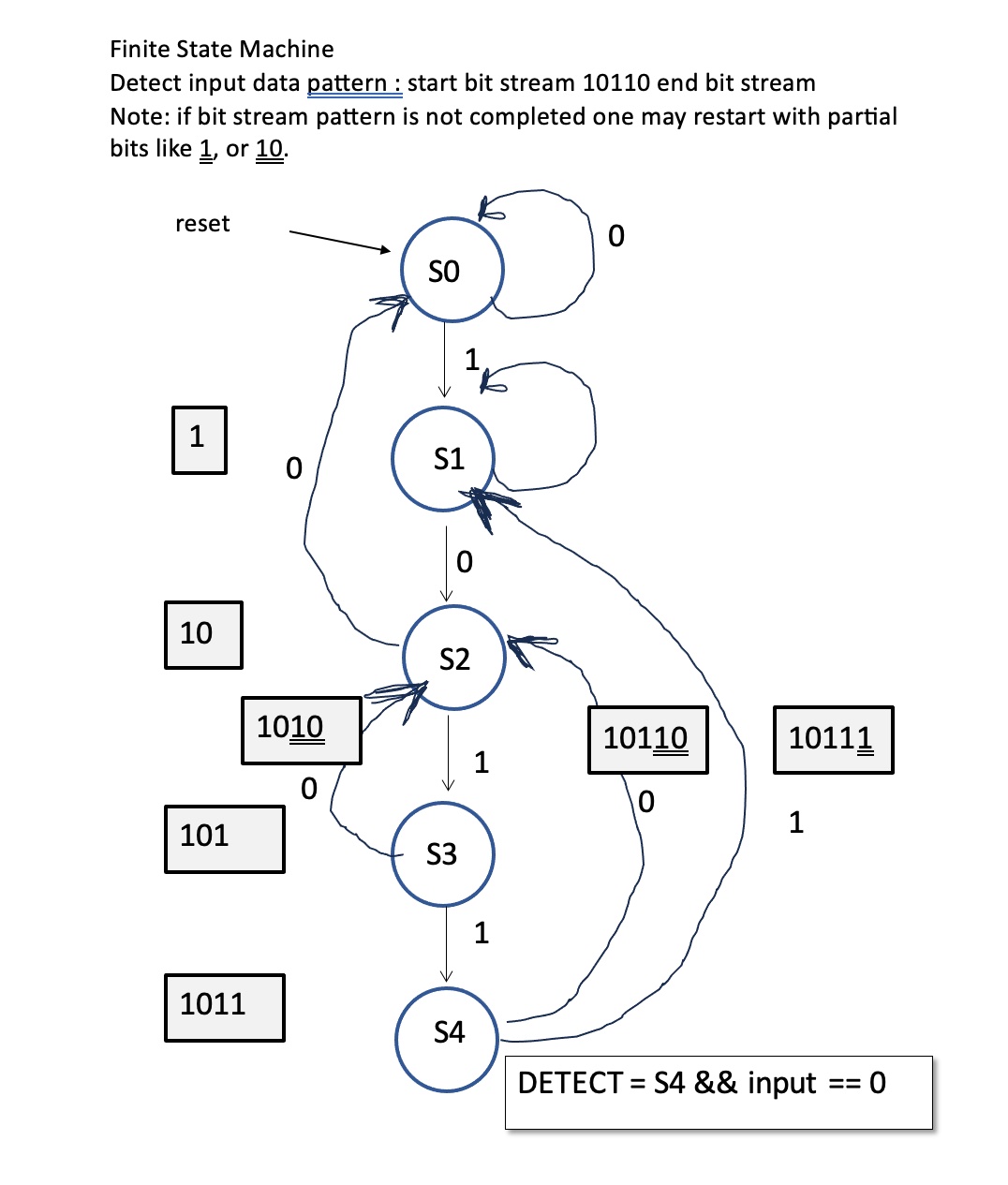
FSM (finite state machine) example : serial bit stream algorithm to detect start with “1” 10110 and end with “0”.
Step 1: Define states and transitions
Start with reset which becomes State 0 (S0)S0 : If data == 0 then loop back to S0
else if data == 1 then transition to S1 [1]
S1 [1] : if data == 0 then transition to S2 (detected pattern [10])
else if data == 1 then loop back to S1 (detected a [1])
S2 [10] : if data == 0 then transition to S0 (detected 100 pattern which doesn’t exist so start all over a wait for a 1 input)
else if data == 1 then transition to S3 (detected pattern [101])
S3 [101] : if data == 0 then transition to S2 (detected 1010 pattern which is basically [10])
else if data == 1 then transition to S4 (detected pattern [1011])
S4 [1011] : if data == 0 then transition to S2 (possible [10] pattern) (detected pattern [10110]) output DETECT signal
else if data ==1 then transition to S1 (detected [1] pattern)
Step 2 – Convert FSM to verilog
to be added
FSM example : traffic controller algorithm
Step 1 – Define states and transition states
// traffic controller
// assume red,yellow,green light for highway East/West
// this becomes the out_fast[2:0] = red,yellow,green
// assume red,yellow,green light for road North/South
// this becomes the out_slow[2:0] = red,yellow,green
// assume highway has priority and always green
// assume sensor is on road North and South side to detect car
module traffic_controller (clk, sensor, reset, out_fast, out_slow);
input clk;
input sensor;
input reset;
output reg [2:0] out_fast; // red, yellow, green
output reg [2:0] out_slow; // red, yellow, green
// 6 possible states but can be reduced
// fast_green
// fast_yellow
// fast_red
// slow_green
// slow_yellow
// slow_red
// or since fast_green means slow_red
// we can encode the states into 4 instead of 6 states
// assume fast_green and slow_red = 2’b00
// assume fast_yellow and slow_red = 2’b01
// assume fast_red and slow_green = 2’b10
// assume fast_red and slow_yellow = 2’b11
parameter FGREEN_SRED = 2’b00;
parameter FYELLOW_SRED = 2’b01;
parameter FRED_SGREEN = 2’b10;
parameter FRED_SYELLOW = 2’b11;
reg [1:0] current_state, next_state;
// next state
always @(*)
begin
case(current_state)
FGREEN_SRED: begin
out_fast = 3’b001; // green highway
out_slow = 3’b100; // red farm
if (sensor) // sensor detects vehicle on farm road then turn light on highway to yellow
next_state = FYELLOW_SRED;
else
next_state = FGREEN_SRED; // keep green highway and red farm
end
FYELLOW_SRED: begin
out_fast = 3’b010; // yellow highway
out_slow = 3’b100; // red farm
// change to next state of Fast red and slow green
next_state = FRED_SGREEN;
end
FRED_SGREEN: begin
out_fast = 3’b100; // red highway
out_slow = 3’b001; // green farm
// change to next state of Fast red and slow yellow
next_state = FRED_SYELLOW;
end
FRED_SYELLOW: begin
out_fast = 3’b100; // red highway
out_slow = 3’b010; // yellow farm
// change to next state of fast green and slow red
next_state = FGREEN_SRED;
end
default: next_state = FGREEN_SRED;
endcase
end
// current state
always @(posedge clk or posedge reset)
begin
if (reset)
current_state <= 3’b000;
else
current_state <= next_state;
end
endmodule
module main;
reg clk = 0;
reg reset = 1;
reg sensor = 0;
wire [2:0] out_fast, out_slow;
// instantiate traffic controller
traffic_controller itc (clk, sensor, reset, out_fast, out_slow);
initial
begin
#5 clk = !clk;
end
initial
begin
$display(“Hello, World: It’s zero time”, $time);
# 1 ; $display(“clk = %b, out_fast = %b, out_slow = %b, time = %0t”, clk, out_fast, out_slow, $time);
# 1 ; $display(“clk = %b, out_fast = %b, out_slow = %b,time = %0t”, clk, out_fast, out_slow, $time);
# 5 ; $display(“clk = %b, out_fast = %b, out_slow = %b,time = %0t”, clk, out_fast, out_slow, $time);
$finish ;
end
endmodule
IEEE 754 Floating Point Standard – Single Precision
IEEE 754 Floating Point Standard
· IEEE has developed a standard for both 32 and 64 bits floating point representation
· The standard was targeted to be used in Personal Computer (IBM-type PC and Apple Macintosh)
· Apple Macintosh also provides its own 80-bit format
· IEEE 754 defines a 32-bits format called single-precision floating point format
o Leftmost bit is the mantissa sign (0 for positive and 1 for negative)
o Followed by 8 bits exponent
o Followed by 24 bit mantissa (23 bits + implied which is always assumed to be 1)
o Exponent is represented using Excess-127 which gives an exponent range of: 2-126 to 2+127
Exponents 0 (2-127) and 255 (2+128) are reserved for special use
o Implied exponent base is 2
o Fraction point position is to right of the leading mantissa bit
o Special numbers (e.g. 0, ∞, very small none normalized numbers, etc.) are supported
o Supported precession is approximately 7 decimal significant digits
o Allows for approximate range of 10-45 to 10+38
· IEEE 754 defines a 64-bits format called double-precision floating point format
o It works similar to the single-precision format
o 11 bits for exponent and 52 bits for mantissa
o Supported precession is approximately 15 decimal significant digits
o Allows for approximate range of 10-300 to 10+300
Convert Decimal Real Number to IEEE 754 Floating Point Format
· The following steps provide the method to convert a decimal real number to IEEE 754 Floating Point format:
o Convert the decimal number to binary
o Adjust binary point to proper position
o Normalize the number
o Convert exponent from sign-and-magnitude to Excess-127
o Convert exponent to binary
o Store the number in the floating point format
1. Convert 36.510 to single-precision IEEE 754 floating point format
1. Convert to binary = 100100.1
2. Adjust binary point to proper position = 1.001001 x 25
3. Normalize already normalized
4. Convert exponent to Excess-127 = 127 + 5 = 132
5. Convert exponent to binary = 10000100
6. Store in floating point format = 0 10000100 00100100000000000000000
2. Convert –0.25 to single-precision IEEE 754 floating point format
1. Convert to binary = .01
2. Adjust binary point to proper position = 0.1 x 2-1
3. Normalize = 1.0 x 2-2
4. Convert exponent to Excess-127 = 127 – 2 = 125
5. Convert exponent to binary = 01111101
6. Convert to floating point format = 1 01111101 00000000000000000000000
Convert from IEEE 754 Floating Point Format to real number
· The following steps provide the method to convert IEEE 754 Floating Point to decimal real number:
o Convert exponent from binary to decimal
o Convert from Excess-127 to sign-and-magnitude
o Convert to exponent notation
o Remove exponent (if possible)
o Convert from binary to decimal real number
1. Convert 1 01111101 00000000000000000000000 to decimal real number
1. Convert exponent to decimal = 125
2. Convert Excess-127 to sign-and-magnitude = 125 – 127 = -2
3. Convert to exponent notation = – 1.0 x 2-2
4. Remove exponent = – 0.01
5. Convert to decimal real number = – 0.25
2. Convert 0 10000001 11001100000000000000000 to decimal real number
1. Convert exponent to decimal = 129
2. Convert Excess to Exponent = 129 – 127 = 2
3. Convert to exponent notation = 1.110011 x 22
4. Remove exponent = 111.0011
5. Convert to decimal real number = 7.1875
Floating Point Number Representation
Floating point numbers are used to represent noninteger fractional numbers and are used in most engineering and technical calculations, for example, 3.256, 2.1, and 0.0036. The most commonly used floating point standard is the IEEE standard. According to this standard, floating point numbers are represented with 32 bits (single precision) or 64 bits (double precision).
In this section, we will look at the format of 32-bit floating point numbers only and see how mathematical operations can be performed with such numbers.
According to the IEEE standard, 32-bit floating point numbers are represented as follows:
3130 2322 0 0 0XXXXXXXXXXXXXXXXXXXXXXXXXXXXXXXX↑↑↑signexponentmantissa
The most significant bit indicates sign of the number, where 0 indicates positive and 1 indicates negative.
The 8-bit exponent shows the power of the number. To make the calculations easy, the sign of the exponent is not shown, but instead excess 128 numbering system is used. Thus, to find the real exponent, we have to subtract 127 from the given exponent. For example, if the mantissa is “10000000,” the real value of the mantissa is 128 − 127 = 1.
The mantissa is 23 bits wide and represents the increasing negative powers of 2. For example, if we assume that the mantissa is “1110000000000000000000,” the value of this mantissa is calculated as follows: 2−1 + 2−2 + 2−3 = 7/8.
The decimal equivalent of a floating point number can be calculated using the following formula:
Number=(−1)s 2**(e−127) 1⋅f,where s=0 for positive numbers, s=1 for negative numbers,e=exponent (between 0 and 255), and f=mantissa.
As shown in the above formula, there is a hidden “1” before the mantissa; i.e., mantissa is shown as “1 · f.”
The largest and the smallest numbers in 32-bit floating point format are as follows:
0 11111110 11111111111111111111111
This number is (2 − 2−23) 2127 or decimal 3.403 × 1038. The numbers keep their precision up to six digits after the decimal point.
0 00000001 00000000000000000000000
This number is 2−126 or decimal 1.175 × 10−38.
4bit ALU example
to be added
Signed adder with two different bit lengths example
to be added
4×4 unsigned Multiplier example
to be added
4×4 signed multiplier example
to be added
FIFO depth calculation
How deep does a FIFO need to be to prevent overflow or underflow?
This scheme is based upon maximum INGRESS (input) rate and maximum OUTGRESS (drain) rate
First establish the maximum INGRESS (input) rate
Second, determine the maximum OUTGRESS (drain) rate
Third, the difference between INGRESS – OUTGRESS becomes the FIFO DEPTH needed to prevent overflow.
GIVEN : Input FREQ A is 1/4 Output FREQ B
Period B enable = Period A enable * 100 (this becomes the BURST LENGTH)
or turned around 100 Period A enables are bursting to become one Period B enable
Duty Cycle B = 25% (this means reading is performed 1/4 of total burst time)
Assuming clk_B = 100 MHz or 10ns period, then clk_A = 100MHz/4 = 25 MHz or 40ns
So total write BURST time = 40 ns * 100 = 4000 ns
So total read BURST time = 1/4 of total write BURST time = 4000/4 = 1000 ns
So FIFO should be able to hold for 4000 – 1000 = 3000 ns
So number of data items can be read in a period of 3000 ns = 3000 ns/40ns = 75
So minimum depth of the FIFO should be 75.
SYSTEMVERILOG ASSERTION TO FORMALLY CHECK CONNECTIONS
always_comb
con_check: assert #0 ianalog.bity==ireg.bitx; else $error(“Connectivity from register bit x to analog input bity is not satisfied”);
FIFO synchronous example
to be added
FIFO asynchronous example
to be added
IEEE floating point addition example
to be added
IEEE 754 floating point comparator example
/*
- Do not change Module name
*/
// IEEE 754 binary32 : one bit sign, 8 bit exponent, 23 bit fraction bits
// David Fong
module fp_compare (
input [31:0] float_a, // float A
input [31:0] float_b, // float B
output reg greater_than, // A > B
output reg less_than, // A < B output
output reg equal); // A = B;
reg [31:31] sign_a, sign_b;
reg [30:23] exp_a, exp_b;
reg [22:0] mant_a, mant_b;
// systemverilog
//always @* begin
// use regular verilog
always @ (float_a, float_b) begin
// systemverilog
/*
reg [31:31] sign_a, sign_b;
reg [30:23] exp_a, exp_b;
reg [22:0] mant_a, mant_b;
*/
sign_a = float_a[31];
sign_b = float_b[31];
exp_a = float_a[30:23];
exp_b = float_b[30:23];
mant_a = float_a[22:0];
mant_b = float_b[22:0];
// compare signs
if (sign_a < sign_b) begin // 0 means pos, 1 means neg greater_than = 1; less_than = 0; equal = 0; end else if (sign_a > sign_b) begin
greater_than = 0;
less_than = 1;
equal = 0;
end else begin
// compare exponent assuming unsigned 0 to 255
if (exp_a > exp_b) begin
greater_than = 1;
less_than = 0;
equal = 0;
end else if (exp_a < exp_b) begin greater_than = 0; less_than = 1; equal = 0; end else begin // compare mantissa portion if (mant_a > mant_b) begin
greater_than = 1;
less_than = 0;
equal = 0;
end else if (mant_a < mant_b) begin
greater_than = 0;
less_than = 1;
equal = 0;
end else begin // last begin
// Numbers are equal
greater_than = 0;
less_than = 0;
equal = 1;
end // matching last end
end
end
end // matching always begin
endmodule
module main;
  reg [31:0] ia ;
  reg [31:0] ib ;
  wire gt,lt,eq;
  fp_compare ifp_compare(ia, ib, gt, lt, eq);
initial
begin
  $display("Hello, World");
  ia = 32'h0;
  ib = 32'h0;
  #10;
  $display("=========================");
  $display("EXERCISE SIGN BIT TESTING");
  $display("%t : ia and ib = 0 so expect eq=1", $time);
  $display("%t : ia = %h, ib = %h, gt = %b, lt = %b, eq = %b", $time, ia, ib, gt, lt, eq);
  ia = 32'h80000000;
  ib = 32'h0;
  #10;
  $display("%t : ia is negative fp number, so expect lt=1", $time);
  $display("%t : ia = %h, ib = %h, gt = %b, lt = %b, eq = %b", $time, ia, ib, gt, lt, eq);
  ib = 32'h80000000;
  ia = 32'h0;
  #10;
  $display("%t : ib is negative fp number, so expect gt=1, ", $time);
  $display("%t : ia = %h, ib = %h, gt = %b, lt = %b, eq = %b", $time, ia, ib, gt, lt, eq);
  #10;
  $display("=========================");
  $display("EXERCISE EXPONENT BIT TESTING");
  ia = 32'h70000000;
  ib = 32'h0;
  #10;
  $display("%t : ia has an exponent bit, so expect gt=1, ", $time);
  $display("%t : ia = %h, ib = %h, gt = %b, lt = %b, eq = %b", $time, ia, ib, gt, lt, eq);
  ia = 32'h70000000;
  ib = 32'h71000000;
  #10;
  $display("%t : ib has larger exponent bit value, so expect lt=1, ", $time);
  $display("%t : ia = %h, ib = %h, gt = %b, lt = %b, eq = %b", $time, ia, ib, gt, lt, eq);
  ia = 32'h71000000;
  ib = 32'h71000000;
  #10;
  $display("%t : ia and ib has same exponent bit value, so expect eq=1, ", $time);
  $display("%t : ia = %h, ib = %h, gt = %b, lt = %b, eq = %b", $time, ia, ib, gt, lt, eq);
  $display("=========================");
  $display("EXERCISE 23 BIT SIGNFICANT TESTING");
  ia = 32'h007FFFFF; // all 24 bits are 1's
  ib = 32'h007FFFFF;
  #10;
  $display("%t : ia = ib 23 bits, so expect eq=1, ", $time);
  $display("%t : ia = %h, ib = %h, gt = %b, lt = %b, eq = %b", $time, ia, ib, gt, lt, eq);
  ia = 32'h007FFFF0;
  ib = 32'h007FFFFF;
  #10;
  $display("%t : ib has larger bit value, so expect lt=1, ", $time);
  $display("%t : ia = %h, ib = %h, gt = %b, lt = %b, eq = %b", $time, ia, ib, gt, lt, eq);
  ia = 32'h71000000;
  ib = 32'h71000000;
  #10;
  $display("%t : ia has larger bit value, so expect eq=1, ", $time);
  $display("%t : ia = %h, ib = %h, gt = %b, lt = %b, eq = %b", $time, ia, ib, gt, lt, eq);
  $finish ;
end
endmodule
Simulation results for IEEE 754 floating point comparator : greater_than, less_than, equal
Hello, World
=========================
EXERCISE SIGN BIT TESTING
10 : ia and ib = 0 so expect eq=1
10 : ia = 00000000, ib = 00000000, gt = 0, lt = 0, eq = 1
20 : ia is negative fp number, so expect lt=1
20 : ia = 80000000, ib = 00000000, gt = 0, lt = 1, eq = 0
30 : ib is negative fp number, so expect gt=1,
30 : ia = 00000000, ib = 80000000, gt = 1, lt = 0, eq = 0
=========================
EXERCISE EXPONENT BIT TESTING
50 : ia has an exponent bit, so expect gt=1,
50 : ia = 70000000, ib = 00000000, gt = 1, lt = 0, eq = 0
60 : ib has larger exponent bit value, so expect lt=1,
60 : ia = 70000000, ib = 71000000, gt = 0, lt = 1, eq = 0
70 : ia and ib has same exponent bit value, so expect eq=1,
70 : ia = 71000000, ib = 71000000, gt = 0, lt = 0, eq = 1
=========================
EXERCISE 23 BIT SIGNFICANT TESTING
80 : ia = ib 23 bits, so expect eq=1,
80 : ia = 007fffff, ib = 007fffff, gt = 0, lt = 0, eq = 1
90 : ib has larger bit value, so expect lt=1,
90 : ia = 007ffff0, ib = 007fffff, gt = 0, lt = 1, eq = 0
100 : ia has larger bit value, so expect eq=1,
100 : ia = 71000000, ib = 71000000, gt = 0, lt = 0, eq = 1
main.v:146: $finish called at 100 (1s)
