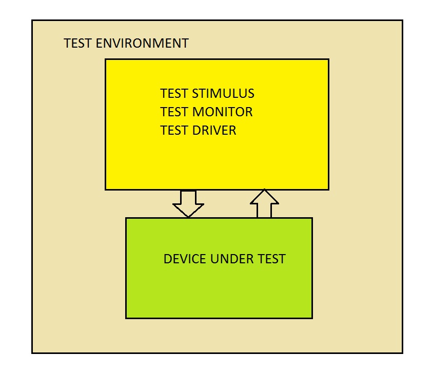
UVM is generally built on a few basic blocks
- DUT (Device Under Test)
- Interface (An interface between DUT and test env)
- Test environment using classes
Simple verilog to display “Hello World”
The module is named top but it can even be “xyz”.
The “initial” statement is what kicks off the run.
///////////////////////////////// VERILOG ONLY /////////////////////////////////
module top;
initial
$display(“Hello World !!”); // verilog only
endmodule
////////////////////////////// END VERILOG ONLY /////////////////////////
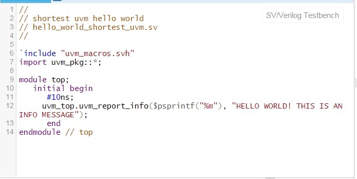
Simple systemverilog code with UVM code to say “Hello World”
// usually test environments use the name top but one can call it anything because the environment is kicked off by the the code enclosed by “initial begin” and “end”.
///////////////////// SYSTEMVERILOG WITH UVM BEGIN ////////////////////////
/////////////// SYSTEMVERILOG WITH UVM END //////////////////////////
Before we can code the equivalent systemverilog version, we need to understand how simulation phases work for systemverilog. In systemverilog, multiple steps or phases occur before the final simulation execution. See the steps in the diagram below:
For now, we avoid a complex example and only use a few essential aspects of UVM to build up to the full fledged understanding of UVM phases in next section.
We need to take one step backwards and then take two steps forward by understanding the systemverilog point of view and then add UVM on top of that.
See next section on systemverilog coding of a counter to point out the main pieces of how a systemverilog testbench is constructed, coded and implemented : UVM Tutorial 3 : Systemverilog Testbench Principles

